Replacing the Battery on the GPS Board
There have been two GPS boards used in the NexStar 8/9.25/11 GPS scopes.
The first was manufactured by Motorola and appeared in the earliest NexStar
8 and 11 GPS models. More recently, Celestron switched to a more
generic board from a couple of vendors.
The external CN-16 GPS unit uses the
newer receiver as found in the newer NexStar GPS scopes.
The CPC scopes use yet another GPS receiver in which the receiver and antenna
are a combined unit.
The SkySync GPS unit should use either a receiver similar to the CPC scopes
or the CN-16 - you will need to open yours to determine which.
As described in
this article, the older GPS modules have a battery which is rechargeable. During
normal use of the scope, the battery is charged by the 12 volts supplied to
the mount. When the battery loses its charge, the hand control will
display the incorrect time until a GPS link is established (normally the GPS
module maintains correct time between uses of the scope). The GPS link
will also take longer than normal. The original
board requires at least 40 hours to completely recharge the battery, while
the newer board requires 24 hours. Disconnect the hand control (to
prevent the scope from tracking while you are away) and power up the scope
to charge the battery.
If the battery will no longer hold a charge, it will be necessary to
replace it.
Click any of the pictures below for a larger version.
|
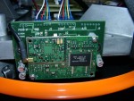
Photo courtesy
Matthias Bopp |
The GPS board for the older NexStar GPS
telescopes is found inside
the base. Using a 3.5mm or 9/64 inch hex wrench, completely
loosen the five screws securing the plastic base cover - the cover
with the Aux, Auto Guide, and PC ports. It is not necessary to remove
the screws as we will only be lifting the cover, not completely
removing it. If you do remove the screws, note that the one in the
back is shorter than the rest.
Carefully lift the base cover. Wires run from the cover to the base
and only allow the cover to be raised about 2 inches (5cm). Put a
rolled-up sock in both gaps between the cover and each fork arm to
hold it in place. The GPS board is on the side opposite the
panel with all the connector ports. The front board shown here
is the GPS board. It is held in place by the two cross-tip
screws in the corners. As you remove these screws and pull the
board free, note the connectors on the back side of the board as well
as the antenna cable. Be sure not to drop the screws into the
base.
The battery is held in a clip and is easily replaced. The
battery is probably a Panasonic ML621 - the one without the solder pins - and is available at
http://www.digikey.com for about $2. Some of the oldest GPS
modules used an ML616 which is no longer available; substitute an
ML614.
When reassembling, be sure the pins on the connectors are well
seated and that all cables are routed so that the scope will rotate
360 degrees without snagging anything.
|
|
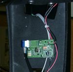
Inside the Fork Arm
Photo courtesy
Matthias Bopp

Outside the Fork Arm
This photo shows the GPS board and the GPS antenna - click for
larger version pointing out the antenna.
Photo courtesy
Rick Smith |
On newer NexStar GPS telescopes the GPS board is found on the
inside of the fork arm with the hand control bracket or on
the outside of the fork arm with the hand control bracket - there is
no way to tell without removing the plastic covers. The CN-16 GPS unit
also uses this same newer GPS board.
If you didn't find the board inside the base as described above,
try the outside of the fork arm - simply remove the large plastic
cover with the hand control holder. Be sure to unplug the hand
control cable first and set the hand control aside.
If you don't find it there, check the inside of the fork arm.
To remove the cover on the inside of the fork arm, you will first need
to lift up the base cover. Use a 3.5mm or 9/64 inch hex wrench and completely loosen the five
screws securing the plastic base cover - the cover with the Aux, Auto
Guide, and PC ports. It is not necessary to remove the screws as we
will only be lifting the cover, not completely removing it. If you do
remove the screws, note that the one in the back is shorter than the
rest. Then remove the four screws holding the plastic cover on
the inside of the fork arm. Pull the cover free and set it
aside.
Note that the battery may be on the side of the board against the
fork arm.
The board
is held in place by two cross-tip screws. Make a sketch of the
cable connection just to be sure you don't misconnect it later.
Remove the screws (be careful not to drop them into the base) and pull
the board free. Here is the complication - as you will see, the
battery is soldered to the board. At this point, if you are
handy with delicate electronics and don't mind the potential risk of
destroying the board, you can unsolder and replace the battery.
Otherwise, contact Celestron about sending the board to them for
battery replacement. The battery is a Panasonic ML2020-H1CN and is
available at
http://www.digikey.com for less than $3. For the CN-16 GPS unit,
open the case and you will see the GPS board mounted within.
Again, it is the same as the board in the late model NexStar 8/9.25/11
GPS telescopes and uses the same ML2020-H1C battery, soldered in place. |
|
On the CPC telescope, the built-in GPS receiver may have a
battery (part number MS621F) or it may have a supercapacitor. In
both cases, the GPS receiver is a combined receiver/antenna and is
generally found at the top of the fork arm with the vertical
carrying handle. David Craig authored an article (which you can
download
here) explaining how to find the GPS receiver and how to open it
to access the battery/capacitor. Additionally it explains a bug with
some CPC mount GPS receivers and how to deal with it (you might not
have a battery problem).
|
|


